Virtual OpenWrt on LXD (redux)

Traffic

Virtual Network in the Palm of your hand

With the latest release of OpenWrt 21.02.0, running a Virtual Router (VR) on Linux Containers (LXD) is much easier, than when I wrote about it back in 2019.

The biggest improvement is that Ubuntu has started to build OpenWrt images on their LXD image server. This allows one to skip all the build-your-own-image steps. Ubuntu is supporting three architectures, x86_64, ARM64, and ARMhf (32 bit). The last is supported on my Raspberry Pi 3b+.

It is now possible to launch an OpenWrt Container with one line (almost). However the Container needs a few fixes after it is launched to work properly.

Motivation, why run OpenWrt in a Container?

Of course, I can run OpenWrt on one of hundreds of real consumer routers, and I do. OpenWrt has excellent IPv6 support, including DHCPv6-PD (prefix delegation), and a really nice web-based firewall configuration.

Why wouldn’t I want that for my virtual machines, as I have for my real ones? Well… I would.

Bridging, the better way to setup LXD

I have been using Linux Containers for a couple of years, and watched people set up LXD in a variety of network configurations, including the default. Unfortunately, even the default network config is not IPv6 friendly.

Setting up a front bridge on the host takes a bit of pre-work, but it is the most transparent way to support IPv6 on your Linux Containers, and also supports running a Virtual OpenWrt router without any additional work.

A front bridge

Bridging is the act of forwarding packets at the ethernet layer. Setting up a front bridge (br0) requires that the host is ethernet attached to the rest of your network. Wifi can not be used, as bridging between Wifi and ethernet requires more than a simple cable plug-in.

Virtual router Network

In the diagram above, br0 is what I am calling a front bridge, everything other than the physical ethernet jack is connected to br0, including the host. Depending on your Linux Distro, this can be daunting to some. Systemd doesn’t help, as it hasn’t really simplified linux networking.

Configure a front bridge

If you haven’t set up a front bridge, see Configuring systemd for a LXD Front Bridge for the 6 easy steps.

Install LXD (if you haven’t already)

If you haven’t already installed LXD on your Raspberry Pi or other Linux machine, please look at Linux Containers on the Pi blog post.

Creating LXD profiles

In order for a Linux Container machine to connect to the network, it needs a profile. The default profile connects the Container to lxdbr0 which is not, by default, connected to anything.

I create a profile to connect my Containers to br0 by default, a profile I call extbridge, which looks like:

$ lxc profile show extbridge
config: {}
description: bridged networking LXD profile
devices:
  eth0:
    name: eth0
    nictype: bridged
    parent: br0
    type: nic
  root:
    path: /
    pool: default
    type: disk
name: extbridge
used_by: []

After I am happy with that profile, I usually just copy it over to the default profile, as most of my Containers are only attached to br0 and get their addressing from the upstream router (both IPv4 & IPv6).

lxc profile copy extbridge default

Creating a profile for OpenWrt

OpenWrt requires two interfaces in order to route. As the earlier diagram shows, the OpenWrt will be routing between br0 and lxdbr0.

Interestingly, when I first used OpenWrt 21.02.0 as a container, the interfaces were reversed (from my previous articles). So I created another profile with eth0 as the WAN, and eth1 as the LAN. (which I call two intf rev, for reversed)

Create twointfrev profile

lxc profile create twointfrev
lxc profile edit twointfrev
    config: {}
    description: 2 interfaces
    devices:
      eth0:
        name: eth0
        nictype: bridged
        parent: br0
        type: nic
      eth1:
        name: eth1
        nictype: bridged
        parent: lxdbr0
        type: nic
      root:
        path: /
        pool: default
        type: disk
    name: twointfrev
    used_by: []

Launch the OpenWrt container

Finally, we get to the easy part. After all the prep of setting up br0, and the twointfrev profile, launching the container is anti-climatic.

lxc launch -p twointfrev images:openwrt/21.02 router21

LXD will automagically pull down the image from the image server, and create a Container named router21.

Fixing the OpenWrt Container

Unfortunately, you will notice that the WAN (eth0) interface will have an IPv4 and IPv6 address, the LAN address will not.

$ lxc ls router21
+----------+---------+-------------------+-----------------------------------------------+-----------+-----------+
|   NAME   |  STATE  |       IPV4        |                     IPV6                      |   TYPE    | SNAPSHOTS |
+----------+---------+-------------------+-----------------------------------------------+-----------+-----------+
| router21 | RUNNING | 10.1.1.108 (eth0) |  2001:db8:8011:fd00::599 (eth0)               | CONTAINER | 0         |
|          |         |                   |  2001:db8:8011:fd00:216:3eff:fef1:25d8 (eth0) |           |           |
+----------+---------+-------------------+-----------------------------------------------+-----------+-----------+

For whatever reason, there are parts missing in this image, most notably the br-lan bridge. Hopefully this will be addressed in future OpenWrt images. But for now, we need to connect to the OpenWrt CLI and do some fixing.

We’ll use LXD’s console access:

lxc exec router21 sh

BusyBox v1.33.1 (2021-08-31 22:20:08 UTC) built-in shell (ash)

~ # 
  1. The following commands will all be done on the OpenWrt CLI. First, create a bridge & br-lan interface. Edit /etc/config/network, add/edit:
config interface 'wan6'
    option reqprefix 'auto'

config device
        option type 'bridge'
        option name 'br-lan'
        list ports 'eth1'
        option bridge_empty '1'

config interface 'lan'
        option proto 'static'
        option device 'br-lan'
        option ipaddr '192.168.88.1'
        option netmask '255.255.255.0'
        option ip6assign '64' 

Note, assign an IPv4 address that works for your network, I chose 192.168.88.1 for my network.

  1. Allow external web management. Edit /etc/config/firewall, add at the bottom of the file:
config rule               
    option target 'ACCEPT'
    option src 'wan'      
    option proto 'tcp'    
    option dest_port '80' 
    option name 'ext_web' 
  1. Restart networking & firewall for changes to take effect
/etc/init.d/network restart
/etc/init.d/firewall restart

OPTIONAL set ULA

  1. Global ULA configuration is not available in Luci – and must be configured manually
uci set network.globals=globals
uci set network.globals.ula_prefix='fdb5:df0c:2121::/64'
uci commit

You will now see the global ULA on the LAN interface now

Exit the LXD console to return to your LXD host

exit
$

Managing the OpenWrt Virtual Router (VR) from a Web Browser

Now you should be able to point your web browser to the WAN address (see output of lxc ls router21 eth0 address). and login, password is blank.

http://[2001:db8:ebbd:2080::599]/

Follow the instructions to set a password, and configure the firewall as you like.

Virtual router Network

Managing your shiny new VR

The OpenWrt router should work just like a real one. This includes the warning message you receive, the first time you click on Network->Interfaces

Virtual router Network

This happens on real routers as well, just click on Continue and all will be well.

You should see that the router now has received Prefix Delegation (PD) from the upstream router, and has applied that to the LAN interface.

$ lxc ls router21
+----------+---------+-----------------------+-----------------------------------------------+-----------+-----------+
|   NAME   |  STATE  |         IPV4          |                     IPV6                      |   TYPE    | SNAPSHOTS |
+----------+---------+-----------------------+-----------------------------------------------+-----------+-----------+
| router21 | RUNNING | 192.168.88.1 (br-lan) |  2001:db8:8011:fd04::1 (br-lan)               | CONTAINER | 0         |
|          |         | 10.1.1.35 (eth0)      |  2001:db8:8011:fd00::11b (eth0)               |           |           |
|          |         |                       |  2001:db8:8011:fd00:216:3eff:feb7:c2be (eth0) |           |           |
+----------+---------+-----------------------+-----------------------------------------------+-----------+-----------+

Address Stability of OpenWrt on LXD

Because all of this is running on LXD, there is address stability. No matter how many times you reboot the Raspberry Pi/Linux host, or restart containers in different order, the addresses remain the same. This means the addresses above can be entered into your DNS server with out churn.

Excellent IPv6 support

LXD is the best at container customization, and virtual networking (IPv4 and IPv6). With LXDs flexibility, it is easy to create templates to scale up multiple applications (e.g. a webserver farm running in the palm of your hand). OpenWrt is one of the best Open source router projects, and now it can be run virtually as well. Now you have a server farm in the palm of your hand, with excellent IPv6 support and a great firewall!


Notes:

  • some of the screen shots are from a Pi host, and others from an AMD host.
  • IPv6 addresses have been changed to conform with Documentation addresses RFC 3849

Palm Photo by Alie Koshes

Virtual hosting, the IPv6 way

Mesh

Virtual Hosting, the IPv6 Way


Virtual Hosting: The act of hosting several web servers on a single piece of hardware

Before there were VM (Virtual Machines), Containers (light-weight VMs), VPS (Virtual Private Servers), there was a need to host multiple servers on a single machine. In the 1990s the internet was exploding, and everyone wanted to have their own web site. The concept of running multiple web servers on a single piece of hardware was created, and implemented in one of the first open source webservers, Apache.

Virtual Hosting, the Old Way

Apache implemented virtual hosting by having the server examine the HTTP Header looking for the Host Field. Based on the Host Field the web server would utilize a specific configuration for that Virtual web server, and serve up files based on that configuration.

A typical Apache Configuration would be:

<VirtualHost *:80>
    ServerAdmin webmaster@localhost
    ServerName www.makikiweb.com
    DocumentRoot /home/makiki/
    <Directory />
        Options FollowSymLinks
        AllowOverride None
    </Directory>
</VirtualHost>

The advantage of the Apache VirtualHost was that back in the days of IPv4, a single IP address could server many, many websites. This was good for the conservation of IPv4 address space.

However, sharing a single IP address means that you can’t get to the website by IP address alone:

IPv4 only addressing

Virtual Hosting, the IPv6 Way

With seemingly inexhaustible amount IPv6 address space, it is time to rethink how we implement Virtual Hosting. We no longer need to share a single IP address for a stable of servers.

It is possible to add many IP addresses to the web server host

$ ip addr
1: lo: <LOOPBACK,UP,LOWER_UP> mtu 65536 qdisc noqueue state UNKNOWN group default qlen 1000
    link/loopback 00:00:00:00:00:00 brd 00:00:00:00:00:00
    inet 127.0.0.1/8 scope host lo
       valid_lft forever preferred_lft forever
    inet6 ::1/128 scope host 
       valid_lft forever preferred_lft forever
2: eth0: <BROADCAST,MULTICAST,UP,LOWER_UP> mtu 1500 qdisc pfifo_fast state UP group default qlen 1000
    link/ether b8:27:cb:bf:52:9c brd ff:ff:ff:ff:ff:ff
    inet6 2001:db8:8:78::f03/64 scope global 
       valid_lft forever preferred_lft forever
    inet6 2001:db8:8:78::f02/64 scope global 
       valid_lft forever preferred_lft forever
    inet6 2001:db8:8:78::f01/64 scope global 
       valid_lft forever preferred_lft forever
    inet6 2001:db8:8:78::102/64 scope global 
       valid_lft forever preferred_lft forever
    inet6 2001:db8:8:78::101/64 scope global 
       valid_lft forever preferred_lft forever
    inet6 2001:db8:8:78::100/64 scope global 
       valid_lft forever preferred_lft forever
    inet6 2001:db8:8:78::1/64 scope global 
       valid_lft forever preferred_lft forever
    inet6 fe80::ba27:cbff:febf:529c/64 scope link 
       valid_lft forever preferred_lft forever

Now each Virtual web server can to have its own IPv6 address. This allows the web server to direct the request directly to the virtual server based on IP address. Using a more modern web server such as nginx also allows individual configuration for each virtual web server such as support for TLS (or not), Proxy Protocol (or not).

A typical nginx configuration for three virtual hosts would be:

# Server 1 on 2001:db8:8:78::102
server {
    listen [2001:db8:8:78::102]:80 proxy_protocol ;

    # setup to log original client IP address
    # incoming IPv4 requests from two proxies   
    set_real_ip_from  2001:db8:0:80:1000:3b:1:1;
    set_real_ip_from  2001:db8:0:82:1000:3b:1:1;
    real_ip_header    X-Forwarded-For;
    root /home/makiki;
    access_log /var/log/nginx/makiki.log;
    location / {
        index         index.html index.htm;
    }
}

# Server 2 on 2001:db8:8:78::f02
server {
    listen [2001:db8:8:78::f02]:80 ;
    root /home/makiki;
    access_log /var/log/nginx/makiki.log;
    location / {
        index         index.html index.htm;
    }
}

# Server 3 on 2001:db8:8:78::f03
server {
    listen [2001:db8:8:78::f03]:80 ;
    root /home/makikica;
    access_log /var/log/nginx/makikica.log; 
    location / {
            index         index.html index.htm;
    }

Each Virtual web server is listening on a unique address with specific configuration for that web server.

The example above shows:

  • Server 1 & 2 are simulating a dual-stack server with one server listening via the IPv4 reverse proxy, and Server 2 listening directly to IPv6. Both are serving the same content (same Document Root), and logging to the same log file. The log file will have both IPv6 and IPv4 addresses (provided by the proxy_protocol).
  • Server 3 is an IPv6-only server, serving different content.

Having an IP address for each web server also eliminates the dreaded “Sorry…” page, as the web server is no longer reliant on the Host Field to direct the request.

Conclusion

When implementing IPv6 networks and services, it is important to not fall into the same IPv4 design constraints and work-a-rounds in the past. Take some time to think outside the box and create a cleaner design, an IPv6 design.

IPv6-only 802.11s Wireless Mesh Network

Mesh

Mesh Network Concept

Wireless Mesh is the buzzword for the 2020s. In the effort to have wall-to-wall Wifi coverage, SOHO (Small Office/Home Office) router vendors, have carved out a new, more expensive, market niche. If one router is good, then three routers must be better (and more profitable).

In this article, we’ll delve into the technology of IPv6-only Wireless Mesh,  the benefits, and downsides if using a Wireless Mesh, instead of the common traditional single SOHO Wireless Router.

What is Wireless Mesh

Wireless Mesh is a group of routers acting together to provide broader wireless coverage, while creating a non-looping paths through the network. The IEEE (The Institute of Electrical and Electronics Engineers) which brought you Ethernet (802.3) and Wifi (802.11), created an ammendment to the Wifi Standard for wireless mesh called 802.11s in 2012.

There are many commercial offerrings for Wireless Mesh network on the market today. Many extend, or implement proprietary aspects of of mesh networking, which creates vendor lock-in.

Fortunately, OpenWrt, the open-source router software, implements the 802.11s standard, and it is possible to create a multi-node wireless mesh with a variety of router vendor’s products.

Wireless Mesh using OpenWrt & 802.11s

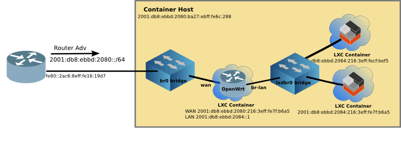
Below is a diagram of a simple 3 node wireless mesh network. The Mesh Portal connects the wireless mesh network to the wired network. The left-most router acts as a Layer 3 (network layer) boundary for the mesh network, providing RA (Router Advertisements), and NAT64/DNS64 services.

Wireless Mesh

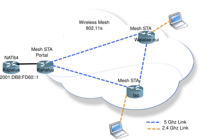
The wireless mesh network is a single L2 domain, all attached devices will be in the same subnet (or IPv6 prefix).

In this mesh network, all nodes are on the same 5 Ghz channel, while the 2.4 Ghz access APs can be on different channels, but share the same SSID to allow wireless devices to easily roam from one mesh node to the next.

Two of the nodes, Waialae-nui and Iao, also server as regular Access Points (AP) allowing wireless nodes to connect to the mesh network.

Looking at 802.11s loop prevention

In order to prevent looping in mesh networks, 802.11s uses Path Discovery using Path Requests (PREQ) and Path Reply (PREP) messages.

Node A looking for a path to Node H. It will flood PREQ messages to all nodes using the ethernet broadcast MAC address. Node H will receive the PREQ message from Nodes F & J, but F will have a lower hop-count, thus the path back to Node A will be via Node F. Node H will send the PREP message back to Node A via the F-D-A path, which Node A will record, noting that the best path from A to H is along the path of A-D-F-H. The use of PREQ and PREP messages remove the possibility of looping in a Mesh network.

Wireless Mesh Path Discovery

PCAP of PREQ & PREP messages

Mesh Networking Addressing, the Air Bridge

A mesh network can be thought of as a giant distributed ethernet bridge forwarding ethernet frames from wired and wireless interfaces across the 802.11s mesh network. In order to transport entire ethernet frames (and their IP payloads) across the wireless mesh, an additional mesh control header is appended after 802.11 header. The Mesh Control Header contain the additional MAC address fields of original source and destination.

In the diagram below, you can see the original sender STA 1 and destination, STA 7 are preserved in Mesh Control Header (as addr 5 & 6) as the packet traverses the mesh network.

Wireless Mesh Path Addressing

PCAP of the Six Addresses used to create the Air Bridge

Determining if your OpenWrt router supports 802.11s

The OpenWrt router must be running version 19.07.x, as wireless mesh is not supported in earlier releases.

802.11s wireless mesh must be supported at the hardware level. In order to determine if your OpenWrt router has this support run the following command:

# iw list | grep mesh
         * mesh point
         * #{ managed } <= 2048, #{ AP, mesh point } <= 8, #{ P2P-client, P2P-GO } <= 1, #{ IBSS } <= 1,
         * mesh point
         * #{ managed } <= 2048, #{ AP, mesh point } <= 8, #{ P2P-client, P2P-GO } <= 1, #{ IBSS } <= 1,

In the above example of dual band router, the * mesh point indicates that it does support 802.11s mesh. The { AP, mesh point } indicates that mesh and AP functionality are simultaneously supported on the same radio.

Configuring OpenWrt for 802.11s Mesh

In order to configure wireless mesh, where all nodes run on the same channel, it is good to scout the area you wish to cover with the wireless mesh network to determine a relatively empty channel. 5 Ghz is the better choice as it has more available non-overlapping channels (9 20 Mhz channels, vs 3 20 Mhz channels on 2.4 Ghz). You may choose to use 40 Mhz channels on the 5 Ghz band, but that reduces the available channels to four. There are the DFS channels (16 20 Mhz, or 8 40 Mhz), but they are not recommended for Wireless Mesh, as nodes will become unavailable, as they move out of the DFS band.

5 Ghz Band

Once you have selected a single channel to be used by your mesh, the following must be done for each of the mesh nodes in your network.

  1. Install a wpad which supports mesh
  2. Add /etc/config/wireless with a mesh interface
  3. And configure mesh channel in /etc/config/wireless
  4. Run the wifi command to reload the wireless config

Before configuring the OpenWrt router for 802.11s, one must remove the default wpad (WPA daemon) and install one that supports mesh networking. Ensure you do this while attached to the router via a wired connection, as you are likely to lose your wireless connection.

opkg remove wpad-mini
opkg remove wpad-basic
opkg install wpad-mesh-openssl

Then add this stanza to the /etc/config/wireless file:

config wifi-iface 'mesh'
        option network 'mesh lan'
        option device 'radio0'
        option mode 'mesh'
        option mesh_id 'mymesh' # anything, this connects the nodes into one mesh (plus the password if there's any)
        option encryption 'psk2/aes' # or 'none'
        option key 'mysecret'   

Change mymesh and mysecret to match your naming and password needs. They must be the same for all mesh nodes

And change the channel of the 5 Ghz Radio to your mesh channel in /etc/config/wireless

config wifi-device 'radio1'
        option type 'mac80211'
        option hwmode '11a'  # indicates the 5Ghz radio
        option path 'pci0000:00/0000:00:00.0'
        option channel '44'  # the Channel to be used for Mesh Network
        option htmode 'HT20'

Run the wifi command to cause OpenWrt to reload the wireless configuration.

Clearly, you will need to run through these steps for each node in your wireless mesh.

Managing the Mesh Nodes

802.11s only provides Layer 2 connectivity between the nodes. In order to be able to manage the nodes the router must be put into dumb AP mode, and assigned a static IP address

In order to not lose connectivity while configuring the router, assign a static IP address to the the LAN interface. Since this is to be an IPv6-only network, assign a static IPv6 address in the same prefix as your IPv6-only network.

Edit the /etc/config/network file, adding ip6gw and ip6addr to the LAN interface. Normally IPv6 gateway addresses are link-local addresses, but that requires interface scope. In this case, it is easier to point back to the NAT64 router’s Global Address (GUA) on LAN interface as the gateway.

For an IPv6-only network, it is OK to leave the IPv4 static address, as it won’t be used, and maybe helpful, to recover the node on your workbench.

config interface 'lan'
        option type 'bridge'
        option ifname 'eth0.1'
        option proto 'static'
        list ipaddr '192.168.222.1/24'
        option ip6gw '2001:db8:8011:fd60::1'
        list ip6addr '2001:db8:8011:fd60::3/64'

To place the router into dumb AP mode, one must disable the DHCPv4 server, and disable IPv6 RA and DHCPv6 services.

Edit /etc/config/dhcp file to disable DHCPv4, and comment out the following lines for RA and DHCPv6 servers on the LAN interface.

config dhcp 'lan'
        option interface 'lan'
        option ignore '1'
        # option ra_management '1'
        # option ra 'server'
        # option dhcpv6 'server'

Ensure that you are connected to the router via the static IPv6 address (it is a good time to put that address in your local DNS server), and restart networking on the router for the changes to take effect.

/etc/init.d/networking restart

Admiring your 802.11s mesh network

In the default OpenWrt configuration, the LAN ports, and the Wireless Radios (2.4 & 5 Ghz) are bridge together. This means by default, the wireless mesh will be bridged to the LAN ports of each router, making it easy to manage by plugging into any LAN port with your laptop.

Since you have already assigned DNS names to the static IPv6 addresses of each node, it is easy to ssh to a node and see if your mesh network is up and running. In this example I’ll ssh to the mesh portal node kahaluu.

$ ssh root@6kahaluu-ap
BusyBox v1.30.1 () built-in shell (ash)

  _______                     ________        __
 |       |.-----.-----.-----.|  |  |  |.----.|  |_
 |   -   ||  _  |  -__|     ||  |  |  ||   _||   _|
 |_______||   __|_____|__|__||________||__|  |____|
          |__| W I R E L E S S   F R E E D O M
 -----------------------------------------------------
 OpenWrt 19.07.4, r11208-ce6496d796
 -----------------------------------------------------
root@Kahaluu:~# 

The iw command will display that status of paths as well as of each peer. The Paths command is a shorter output. Make sure you use the correct wireless interface (wlan0 or wlan1).

root@Kahaluu:~# iw dev wlan0 mpath dump
DEST ADDR         NEXT HOP          IFACE   SN  METRIC  QLEN    EXPTIME     DTIM    DRET    FLAGS
c4:e9:84:2f:4d:de c4:e9:84:2f:4d:de wlan0   69838   326 0   0   100 0   0x4
84:c9:b2:54:30:5c 84:c9:b2:54:30:5c wlan0   0   299 0   0   0   0   0x10

Since this is Layer 2-based, you will only see MAC addresses of each node. It is probably a good time to make a note of each nodes MAC address. The key fields of this output are the Destination Address, Next Hope, and Metric columns. Because this is only a 3 node mesh, the Destination Address and Next Hop will almost always be the same. To see the mesh in action, run the wifi command on another node, while running the MPath on the original node, not that initially, the connectivity will be via the third node, before reverting to a direct connection.

Watching a mesh node reattach

root@Iao:/etc/config# iw dev wlan1 mpath dump
DEST ADDR         NEXT HOP          IFACE   SN  METRIC  QLEN    EXPTIME     DTIM    DRET    FLAGS
84:16:f9:eb:c9:ae 84:c9:b2:54:30:5c wlan1    6   556 0   1260    100 0   0x5
84:c9:b2:54:30:5c 84:c9:b2:54:30:5c wlan1   27943   257 0   1270    100 0   0x15

root@Iao:/etc/config# iw dev wlan1 mpath dump DEST ADDR NEXT HOP IFACE SN METRIC QLEN EXPTIME DTIM DRET FLAGS 84:16:f9:eb:c9:ae 84:16:f9:eb:c9:ae wlan1 9 326 0 3460 200 1 0x5 84:c9:b2:54:30:5c 84:c9:b2:54:30:5c wlan1 27943 257 0 3460 100 0 0x15

root@Iao:/etc/config# iw dev wlan1 mpath dump DEST ADDR NEXT HOP IFACE SN METRIC QLEN EXPTIME DTIM DRET FLAGS 84:16:f9:eb:c9:ae 84:16:f9:eb:c9:ae wlan1 10 358 0 1260 100 0 0x5 84:c9:b2:54:30:5c 84:c9:b2:54:30:5c wlan1 27943 257 0 1260 100 0 0x15


Dumping information about the peer nodes

Using the iw command it is possible to view quite a bit of information about the peer nodes.

root@Kahaluu:~# iw dev wlan0 station dump
Station c4:e9:84:2f:4d:de (on wlan0)
    inactive time:  0 ms
    rx bytes:   1358471
    rx packets: 4338
    tx bytes:   621897
    tx packets: 2269
    tx retries: 85
    tx failed:  1
    rx drop misc:   19
    signal:     -74 [-74] dBm
    signal avg: -74 [-74] dBm
    Toffset:    163995750460 us
    tx bitrate: 65.0 MBit/s MCS 6 short GI
    rx bitrate: 39.0 MBit/s MCS 4
    rx duration:    366589 us
    last ack signal:0 dBm
    expected throughput:    31.218Mbps
    mesh llid:  0
    mesh plid:  0
    mesh plink: ESTAB
    mesh local PS mode: ACTIVE
    mesh peer PS mode:  ACTIVE
    mesh non-peer PS mode:  ACTIVE
    authorized: yes
    authenticated:  yes
    associated: yes
    preamble:   long
    WMM/WME:    yes
    MFP:        yes
    TDLS peer:  no
    DTIM period:    2
    beacon interval:100
    connected time: 114 seconds
Station 84:c9:b2:54:30:5c (on wlan0)
    inactive time:  20 ms
    rx bytes:   366529
    rx packets: 2751
    tx bytes:   621
    tx packets: 4
    tx retries: 0
    tx failed:  0
    rx drop misc:   35
    signal:     -80 [-80] dBm
    signal avg: -79 [-79] dBm
    Toffset:    106140160060 us
    tx bitrate: 6.5 MBit/s MCS 0
    rx bitrate: 45.0 MBit/s MCS 2 40MHz short GI
    rx duration:    60280 us
    mesh llid:  0
    mesh plid:  0
    mesh plink: ESTAB
    mesh local PS mode: ACTIVE
    mesh peer PS mode:  ACTIVE
    mesh non-peer PS mode:  ACTIVE
    authorized: yes
    authenticated:  yes
    associated: yes
    preamble:   long
    WMM/WME:    yes
    MFP:        yes
    TDLS peer:  no
    DTIM period:    2
    beacon interval:100
    connected time: 114 seconds

Key information here is Signal strength, bitrate, and mesh parameters.

Configuring APs on your mesh network

Now that you have your mesh nodes all configured, and peering setup, you still need to configure some (or all) of the Nodes in AP mode. This will allow wireless devices, such as laptops, cell phones, IoT devices, to communicate across your new mesh network.

You have a choice, you can configure an AP on the 5 Ghz interface if your initial HW check displayed { AP, mesh point }. If not, then you will must use the 2.4 Ghz interface as an AP.

Configuring an AP

Configuring an AP on a node is the same as you would configure an AP on a non-mesh network router. It is easier to do via the *LuCI Web Interface, but it can also be done via the CLI.

Edit the /etc/config/wireless file, which should be default already have an AP configuration stanza

config wifi-iface 'default_radio0'
    option device 'radio0'
    option network 'lan'
    option mode 'ap'
    option key 'sEcrEt'
    option ssid 'holoholo'
    option encryption 'psk2'

Update the key with your preferred wireless password, and the SSID with the name of the AP.

Run the wifi command to reload the wireless config

Roaming from AP to AP with 802.11r

In order to enable roaming as you wander around your mesh network, you must use the same key and ssid for all of the APs on the mesh network.

If you want to add 802.11r support (for faster roaming handoff) add the following options to your AP configuration stanza. The mobility domain (4 hex digits) must be the same for each AP that allows roaming.

config wifi-iface 'default_radio0'
       ...
       # 802.11r below
       option ft_over_ds '1'
       option mobility_domain 'EAEA' # four HEX digits, hawaiian for 'air'
       option ft_psk_generate_local '1'
       option ieee80211r '1'

Or use the LuCI web interface and just check the box Wireless Mesh 802.11r

And add a four hex digit mobility domain when the box appears. Wireless Mesh 802.11r

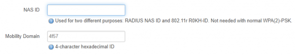
Using your Wireless Mesh Network

Now that the mesh network is up and running, and APs have been configured and enabled, it is time to use the wireless mesh network.

Configure your wireless device to use the shared AP SSID (holoholo in this example).

The NAT64/DNS64 router (kapalua) will provide the IPv6-only addressing across the mesh network and your wireless device will obtain a SLAAC and/or DHCPv6 address.

Once your wireless device has an IPv6 address, the world is at your finger tips.

Downside to using Wireless Mesh

All of those wireless hops come at an additional cost of higher latency and lower throughput. Since each wireless hop must store and forward each packet, there is additional latency added. And if you chose to use 5 Ghz APs, then each AP must share the same access channel as the mesh channel, adding additional latency.

Latency & Throughput

Use ping to measure latency across the mesh network.

$ ping -c10 6paikea.hoomaha.net                    
PING 6paikea.hoomaha.net(2607:c000:8011:fd44:1867:49ff:fee8:555b) 56 data bytes
64 bytes from 2607:c000:8011:fd44:1867:49ff:fee8:555b: icmp_seq=1 ttl=62 time=2.84 ms
64 bytes from 2607:c000:8011:fd44:1867:49ff:fee8:555b: icmp_seq=2 ttl=63 time=9.43 ms
64 bytes from 2607:c000:8011:fd44:1867:49ff:fee8:555b: icmp_seq=3 ttl=63 time=4.50 ms
64 bytes from 2607:c000:8011:fd44:1867:49ff:fee8:555b: icmp_seq=4 ttl=63 time=9.31 ms
64 bytes from 2607:c000:8011:fd44:1867:49ff:fee8:555b: icmp_seq=5 ttl=63 time=9.83 ms
64 bytes from 2607:c000:8011:fd44:1867:49ff:fee8:555b: icmp_seq=6 ttl=63 time=9.45 ms
64 bytes from 2607:c000:8011:fd44:1867:49ff:fee8:555b: icmp_seq=7 ttl=63 time=2.46 ms
64 bytes from 2607:c000:8011:fd44:1867:49ff:fee8:555b: icmp_seq=8 ttl=63 time=5.93 ms
64 bytes from 2607:c000:8011:fd44:1867:49ff:fee8:555b: icmp_seq=9 ttl=63 time=9.03 ms
64 bytes from 2607:c000:8011:fd44:1867:49ff:fee8:555b: icmp_seq=10 ttl=63 time=9.24 ms

--- 6paikea.hoomaha.net ping statistics ---
10 packets transmitted, 10 received, 0% packet loss, time 44ms
rtt min/avg/max/mdev = 2.457/7.202/9.831/2.816 ms

Compared to a wired connection, where the latency is about 1 ms.

Throughput

Transferring a 251 MB video file from RAM disk to RAM disk, using scp on a Raspberry Pi 3B+. All times measured by scp.

Rate Time Comment
7.4MB/ 00:33 Wired with Powerline adapters
20.6MB/s 00:12 Wired GigE on same network
2.6MB/s 01:35 Mesh with 1 hop – same channel
4.0MB/s 01:03 Mesh with 1 hop – 2.4 Ghz access, 5 Ghz Mesh
17.8MB/s 00:14 Direct connect to 802.11n bridged
11.8MB/s 00:21 Direct connect to 802.11ac routered

The 3B+ Pi although equipped with a GigE interface, is throughput limited to 200 Mbit, but that is enough for this testing.

As it can be seen, a traditional router (non-mesh) has much better throughput. And bridged Wifi is faster than routed Wifi (in the traditional router scenarios).

802.11r Fast Roaming Performance

How fast is Fast Roaming (802.11r)? Walking between two APs, noted an extra long ping when the switch happens.

$ ping 6paikea.hoomaha.net
PING 6paikea.hoomaha.net(2607:c000:8011:fd44:1867:49ff:fee8:555b) 56 data bytes
64 bytes from 2607:c000:8011:fd44:1867:49ff:fee8:555b: icmp_seq=1 ttl=62 time=8.70 ms
64 bytes from 2607:c000:8011:fd44:1867:49ff:fee8:555b: icmp_seq=2 ttl=63 time=8.65 ms
64 bytes from 2607:c000:8011:fd44:1867:49ff:fee8:555b: icmp_seq=3 ttl=63 time=8.40 ms
...
64 bytes from 2607:c000:8011:fd44:1867:49ff:fee8:555b: icmp_seq=27 ttl=63 time=3.97 ms
64 bytes from 2607:c000:8011:fd44:1867:49ff:fee8:555b: icmp_seq=28 ttl=63 time=403 ms  <====
64 bytes from 2607:c000:8011:fd44:1867:49ff:fee8:555b: icmp_seq=29 ttl=63 time=3.46 ms
64 bytes from 2607:c000:8011:fd44:1867:49ff:fee8:555b: icmp_seq=30 ttl=63 time=10.1 ms
64 bytes from 2607:c000:8011:fd44:1867:49ff:fee8:555b: icmp_seq=31 ttl=63 time=15.9 ms

Without 802.11r enabled, I noted that my test the wireless device (a Chromebook) would not switch APs, even though the Chromebook was right next to another AP until it was put to sleep and reawakened.

IPv6 Support

Since 802.11s wireless mesh, is a layer 2 protocol, it is possible to configure an IPv6-only network on top of the mesh network.

Wireless Mesh

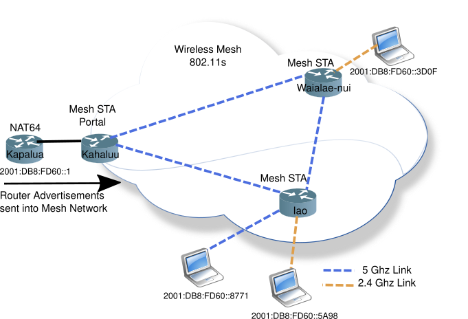
Router Advertisements are sent into the mesh network normally, as one would expect. Neighbour discovery (NDP) which also uses multicast works correctly.

Of course, one doesn’t need to run an IPv6-only network as part of a wireless mesh network, but many issues can be flushed out by running IPv6-only.

Conclusion: A matter of size

Looking at the Commercial Wireless Mesh Products online, the prices range from about $200-$1000. All of them make claims of covering 400-600 m2 (4000 to 6000 square feet). That is a really large house, or you just want to give your horses Wifi in the barn.

Perhaps only a distant room or office requires a stronger wireless signal. OpenWrt supports Wireless Distribution System (WDS), which is much easier to configure, can easily extend your wireless coverage.

Wireless mesh has its place in large area loop-free distribution of wireless networking. However, most SOHO (Small Office/Home Office) environments will not require the broad area coverage that 802.11s provides.

More info

Originally published on www.makiki.ca

Accessing IPv4-only Nodes from an IPv6-only Network

Wayland

Getting from here to there

The Transition to IPv6 has been long, and slow. We have reached a stage where many networks are dual-stack, supporting both IPv4 and IPv6. But dual-stack is not the end game. The final picture is to just support IPv6, making everything easy again with only one set of firewall rules, one set of routing tables, one set of everything.

The Real World

But in the real world, IPv4 is going to be with us for a long time. There will be inexpensive devices, such as IoT which will be IPv4-only.

So how do we transition to IPv6-only, which will make everything easier to managed (only having one set of things to manage) and still have a small number of IPv4-only devices on the network?

IPv4 aaS

The answer to this real world problem is to support IPv4-as-a-Service (IPv4aaS). Create islands, or corners of IPv4 support where you need it, while running the bulk of the network as IPv6-only.

But there is no compatibility between IPv4 and IPv6, so how is this done? Through Transition Technologies such as 464XLAT (v4 to v6 to v4 Translation Technology).

NAT64, the v6 gateway to the v4 Internet

Before digging into IPv4aaS, let’s review NAT64 transition technique. If you have setup a IPv6-only network without NAT64, then you have discovered that while you can get to many things on the internet, there is much you can’t access. Sadly, there are many web sites which are still IPv4-only. Almost all of the Canadian Government’s web sites fall in this category.

So there is a need to access both IPv4 and dual-stack web sites on your IPv6-only network. A NAT64 will translate your IPv6 packets to IPv4. It works in conjuction with DNS64, a special server which translates IPv4 addresses to synthesized IPv6 addresses.

Simple NAT64/DNS64 Network

Host N6 will make a DNS Query for Host N4 from the DNS64 server. A synthesized IPv6 address of 64:ff9b::c000:201. Host N6 will use this address as the destination address sending the packet to the NAT64 (router). The NAT64 device will look at the last 32 bits of the IPv6 address and convert it to a 32bit IPv4 address (C0 00 02 01 = 192.0.2.1), where the packet will be sent on the IPv4 network to host N4.

The reverse path works similar to NAT44, where the NAT64 box maintains a table, and translations/forwards an IPv6 packet to Host N6.

Create an IPv4 Island on your IPv6-only network

What if you want to manage an IPv4-only device from your IPv6-only network?

Using a small OpenWrt router, it is possible to create a small dual-stack island network.

Island Network

OpenWrt 19.07.x supports jool a really useful v4<–>v6 translation tool. Using OpenWrt defaults, it will automatically extend your IPv6 network using DHCPv6-PD, assigning a prefix and by default DHCP4 will also be enabled on the br-lan ports. But IPv4 won’t be able to go anywhere, for now.

Install Jool on OpenWrt IPv4 island router

Use the web GUI or CLI to install jool

opkg update
opkg install kmod-jool jool-tools

Using your own IPv6 Address plan, add the following to /etc/rc.local above the last line. If the br-lan already has Prefix Delegation, then I recommend using that prefix, and add another Quibble of 4444 to make it easily recognized as a IPv4 network.

# jool rev nat64 conf
modprobe jool
jool -6 2001:db8:8011:fda4:4444::/96 --force

Reboot the router, or just run rc.local

sh /etc/rc.local

Access a IPv4-only host on the Island Network

Now any IPv4-only device is accessible from your IPv6-only network. Let’s start with ping. For a device with the IPv4 address of 192.168.38.109, I just prepend the prefix that was placed in the rc.local

From my IPv6-only network:

$ ping 2001:db8:8011:fda4:4444::192.168.38.109
PING 2001:db8:8011:fda4:4444::192.168.38.109(2001:db8:8011:fda4:4444:0:c0a8:266d) 56 data bytes
64 bytes from 2001:db8:8011:fda4:4444:0:c0a8:266d: icmp_seq=1 ttl=63 time=3.04 ms
64 bytes from 2001:db8:8011:fda4:4444:0:c0a8:266d: icmp_seq=2 ttl=63 time=10.3 ms
64 bytes from 2001:db8:8011:fda4:4444:0:c0a8:266d: icmp_seq=3 ttl=63 time=10.5 ms
^C
--- 2001:db8:8011:fda4:4444::192.168.38.109 ping statistics ---
3 packets transmitted, 3 received, 0% packet loss, time 5ms
rtt min/avg/max/mdev = 3.044/7.926/10.463/3.454 ms

Note that ping will convert the odd looking IPv6 address (with a dotted decimal last 32 bits) to a more common hexadecimal IPv6 address.

Doing more than Ping

OpenWrt default includes forwarding pings, but if you want to do more, you will need to open some ports on the firewall. The web GUI works well, or you can add the following to the /etc/config/firewall file, which will forward port 22 (ssh) and 80 (web) to the br-lan.

config rule
    option dest_port '22 80'
    option src 'wan'
    option name 'ext_mgmt_fwd'
    option family 'ipv6'
    option target 'ACCEPT'
    option dest 'lan'
    list proto 'tcp'

Accessing the Internet from the Island Network

Unfortunately, the version of Jool is too old (on OpenWrt 19.07.x) to implement CLAT (Customer-side Translator), which provides a method to move IPv4 across an IPv6-only network.

Imagine you have an IPv4-only IoT device which also has local management. As we saw, we can get access to that device from our IPv6-only network. But the IoT device may get Software updates from the internet. For that the Network Island router must also implement CLAT.

Background 464XLAT

A method to move IPv4 across an IPv6 is called 464XLAT, which means take IPv4 move it across IPv6-only network, and then put it on the IPv4 Internet. This allows poorly written, or legacy applications which include IPv4 literals embedded in them to get access to the Internet, across a IPv6-only network.

464XLAT has two parts

  1. CLAT – the client side, that take a IPv4 packet and encloses it in IPv6 to cross the IPv6-only netowrk
  2. PLAT – the Provider side (or Internet side) which receives the special IPv6 packet, and puts the datagram back into a IPv4 packet for transport onto the IPv4 Internet.

Island Network

Together the two parts are known as 464XLAT

Fortunately, our NAT64 server can also serve the function of PLAT. So that part is done.

Implementing CLAT on OpenWrt for the Island Network

Fortunately, CLAT for OpenWrt has been around for several years using another OpenWrt package: 464xlat*. Install the package on your island router like any other software:

opkg install 464xlat

After the install is complete, reboot the router, which will create a WAN6_4 interface.

If you are using the Well Known Prefix (WKP) for NAT64 (64:ff9b::/96), then you are done! CLAT is configured, and up and running.

To prove that the IPv4 Internet is accessible from your IPv4 island network, ssh to a device on the island network, and start a ping to Cloudflare’s server 1.1.1.1

Iot$ ping 1.1.1.1
PING 1.1.1.1 (1.1.1.1): 56 data bytes
64 bytes from 1.1.1.1: seq=0 ttl=57 time=31.117 ms
64 bytes from 1.1.1.1: seq=1 ttl=57 time=31.959 ms
64 bytes from 1.1.1.1: seq=2 ttl=57 time=31.608 ms
^C
--- 1.1.1.1 ping statistics ---
3 packets transmitted, 3 packets received, 0% packet loss
round-trip min/avg/max = 31.117/31.561/31.959 ms

Supporting Legacy devices is easy

Wayland
Create an IPv4 Island Network

Most IPv4-only devices are not high bandwidth, which means a small OpenWrt router such as the GL-iNET Mango can do the job.

Leveraging your existing IPv6-only network, and NAT64/DNS64 services you already have, means you are already 1/2 way to supporting 464XLAT. Creating legacy island networks which can be managed from your IPv6-only network removes the last hurdle to move to IPv6-only everywhere.

By using existing software, jool 464xlat, on Openwrt, it is easy to create IPv4-only islands to support legacy devices in your IPv6-only network!


* The new version of OpenWrt, 21.02, will be out in a couple of months, and the newer version of jool will handle both the IPv6->IPv4 access, and CLAT functionality. The package 464xlat will no longer be needed.


* Article originally published on www.makiki.ca

Prefix Delegation for SOHO

LXD

IPv6 PD in the SOHO

IPv6 has no need for NAT, however, there is a need for a Globally Unique Addresses (GUAs). Therefore your SOHO (Small Office/Home Office) will require a block of GUAs to use. You can either obtain the Block of GUAs from your RIR (Regional Internet Registry, e.g. ARIN for North America and Hawaii), known as PI (Provider Independent).

Or you can use a block of GUAs from your ISP, known as PA (Provider Addresses).

I suspect for the foreseeable future, SOHO will obtain IPv6 addresses from their ISP (or PA Space). PA space is much easier for small organizations which do not have full time IT staff.

Although PI address space has its advantages, such as no address renumbering when changing ISPs, it requires a more sophisticated setup, usually including BGP (Border Gateway Protocol) peering with an ISP.

Prefix Delegation is a method where the ISP will “loan” you some PA Space to use inside your network. Prefix Delegation RFC 3633 standardized the allocation of a block addresses back in 2003. The standard has been updated by RFC 8415 in 2018.

In this article, we’ll pose the following questions, and hopefully provide some answers:

  • What are the basics of Prefix Delegation?
  • What if you have more than one router in your SOHO network?
  • How is IPv6 Prefixes allocated within your network?
  • Why use OpenWrt in your SOHO network?
  • What if your ISP asks you to power cycle your main router? What happens to the other routers?
  • Can deterministic PD address blocks be created with with OpenWrt?
  • Can you create redundancy (or loops) in your network with PD?

Prefix Delegation Basics

Prefix Delegation is implemented as an option within the DHCPv6 spec in RFC 8415, as Option 25 (OPTION_IA_PD). Therefore, DHCPv6 must be used between the router and the upstream device (e.g. ISP router). Once the Delegated Prefix has been allocated by the ISP, the router will apply the Prefix to the internal LAN, hosts on this LAN segment will use the Delegated Prefix to create their own IPv6 GUA (Globally Unique Addresses) using SLAAC (Stateless Address Auto Config), or by making their own DHCPv6 request. Either way, the Hosts on the LAN will have a GUA and can get onto the IPv6 Internet.

Prefix Delegation in a more complex SOHO network

What if you have more than router in your SOHO netowrk? How is IPv6 PD allocated within your network?

Let’s take the following example network with four (4) routers and six (6) netowrks:

SOHO Network Concept

Fig 1: Example Network

Just like above, the WAN Router made a DHCPv6-PD Request to the ISP for a block of IPv6 addresses. The ISP will usually allocate a /56* which can be subdivided into 256 /64 networks. Should be plenty of room.

In the network above, the WAN router has multiple ports, which have been divided into three (3) Networks (Net A, Net B, Net C). These networks may have different purposes, and firewall access rules (such as Production, Printer/IoT, DMZ).

In turn each of the first tier routers (Router A, Router B, Router C) will make DHCPv6-PD request to the WAN Router, and each receive a smaller chunk of the original /56 allocated, to be used downstream (Net Aa, Net Bb, Net Cc).

As you can see Prefix Delegation continues to slice and dice the original /56 in smaller and smaller chunks supplying IPv6 GUA address space downstream.

Prefix Delegation implemented in OpenWrt

Why use OpenWrt in a SOHO environment?

  • Supported on over 1000 home-class routers
  • Inexpensive solution with excellent IPv6 support
  • Includes a consistent web-based GUI for configuration

OpenWrt Prefix Delegation address allocation has its roots in HomeNet RFC 7368. Using the basic algorithm: PD Address Space / Number of LAN Ports = block size per port.

Most home routers have 4 LAN ports, so that a /56 will be divided into /60s to be allocated to the first tier of routers (Router A, Router B, Router C). Each of the first tier routers will in-turn have 4 LAN ports, and allocate 4 x /64 out of each /60.

SOHO Network Concept

Fig 2: Example Network sliced and diced

Now let’s apply some addresses, assuming the ISP has delegated a /56 to our SOHO network.

SOHO Network with addresses

Fig 3: Example Network sliced and diced with addresses

In Figure 3, the ISP Delegated Prefix is 2001:db8:aaaa:bb00::/56 which leaves the last two (2) nibbles (or hexidecimal characters) to be used inside the SOHO network. It is best practice to divide prefixes no smaller than nibble (4 bits). It will make things much easier for you going forward.

OpenWrt will create four (4) blocks of IPv6 addresses from the original /56 and allocate them to each network downstream. In our address example (Fig 3), the blocks would appear as:

2001:db8:aaaa:bb00::/60
2001:db8:aaaa:bb40::/60
2001:db8:aaaa:bb80::/60
2001:db8:aaaa:bbC0::/60

These blocks would in turn be sub-divided by each of the first tier routers (Routers A, Router B, Router C), so that Router A would create another 4 blocks:

2001:db8:aaaa:bb04::/64
2001:db8:aaaa:bb08::/64
2001:db8:aaaa:bb8C::/64
exhaused

And Router C PD blocks would be:

2001:db8:aaaa:bb84::/64
2001:db8:aaaa:b488::/64
2001:db8:aaaa:b88C::/64
exhaused

As you can see there is not enough address space in the /60 to create four (4) /64 address blocks since the Zeroth block (e.g. 2001:db8:aaaa:bb00::/64) has already been allocated.

As you can see Prefix Delegation within your SOHO using OpenWrt makes creating new networks a plug-and-play operation. However, it is not overly efficient with address space.

Prefix Delegation and Routing

What is not obvious, so far, is that not only does Prefix Delegation allocate address blocks down stream, but the router must also insert a route for each PD block allocated. With OpenWrt, this is done automagically for the user. Each tier 1 router will have a default router pointing upstream (toward the WAN Router) and a specific route for the PD block downstream. When the DHCPv6 lease is allowed to expire (e.g. the downstream router was removed), the downstream specific route will be removed.

Power Cycling your Main Router

But what if your ISP suggests you turn your router off and on again (a common refrain of the IT crowd). Since DHCPv6-PD is stateful, all memory of that state will be lost.

Should the WAN Router be power cycled, it will no longer know about the DHCPv6-PD arrangements previous made, and no longer have the PD specific downstream routes. In other words, this will be a bad thing. If you are running a network like Fig. 3, it is best to power cycle routers A, B, and C as well, so they will initiate a new DHCPv6-PD request from the WAN Router, and re-establish the PD address blocks, and specific downstream routes to the tier 1 routers.

Oh, and your address prefix delegations may change

You dutifully power cycled your WAN Router, and tier 1 routers, only to discover that your DNS queries (you are running DNS, right) are replied with the wrong addresses.

There is no guarantee that the LAN ports on the OpenWrt router will come up in the same order as they did before the power cycle, and your /60 may have moved from one port to another (e.g. Router C now has prefix 2001:db8:aaaa:bb40::/60 instead of 2001:db8:aaaa:bb80::/60. This is not only irritating, but can turn a simple action into a bad day

Leveraging PD but with more deterministic address blocks

Fortunately, the devs of OpenWrt create an easy solution to the non-deterministic PD blocks assigned to the downstream ports in the form of a ip6hint. On the WAN Router, enter the ip6hint via the web-based GUI, navigate to Network->Interface->Your interface->Edit->IP6hint

Luci ip6hin6

Save and Apply, and that interface (in Fig 3, connected to Router B) will always use 2001:db8:aaaa:bb40::/60 for prefix delegation. No change needs to be made on Router B itself, since it is receiving the PD from the WAN Router.

Of course, like any linux system, ip6hint can be configured in the /etc/config/network file as well with lines like:

config interface 'DMZ'
    ...
    option ifname 'eth0.3'
    option ip6assign '60'
    option ip6hint '40'
    option mtu '1452'

Then restart the network to apply the change of the configuration file

/etc/init.d/network restart

Networks with loops/redundancy

What if you wanted redundancy in your network? What if Router B went down, or you wanted to upgrade it to the latest OpenWrt? You would want some resiliency or redundancy to your network.

For example by adding yet another router (Router D) to the network, both Network Aa and Bb would have an alternate path should Router A or Router B run into a problem.

SOHO Network with redundancy

Unfortunately, DHCPv6-PD will not help you here. You will need to run a routing protocol such as RIPng. There are better routing protocols, but none so simple to configure. Just turn it on, and forget it, perfect for the SOHO environment.

Fortunately, OpenWrt supports RIPng via the bird routing daemon. To see how to configure it in OpenWrt please refer to RIPng the forgotten routing protocol

Summary: DHCPv6-PD is pretty much plug-and-play

As you can see Prefix Delegation is how each of your hosts in your SOHO network can use a GUA without the complications of NAT. DHCPv6-PD in its simplest form is plug-and-play. But your network may be a bit more complicated, as your business grows more complicated, and knowing how to stabilize PD address allocations will go a long way to keeping your network running smoothly while you concentrate on the more important parts of your business.


* ISPs can delegate blocks as large as a /48, and as small as a /64. /56 seems to be the most common allocation size.

* Originally posted on makiki.ca.

How does your host get DNS? Where is DNS resolved?

DNS

DNS makes it easy

The Modern Internet requires only two things of the internet user:

  • IP address

  • DNS (Domain Name Service)

What is DNS? A globally distributed and resilient database of names to IP addresses (both v4 & v6).

Why do we need it? Because the sheer number of websites and other services on the internet is too large for humans to memorize. It is much easier to name, than an IP address (this is especially true for IPv6).

In this article, we’ll pose questions, and provide answers to the following:

  • How does a host get DNS? DHCP/RA

  • What is DNS Search List, and how does it help?

  • Captive Portals, redirecting DNS requests, how IPv4 and IPv6 are different

  • Where is DNS resolved? Problems with DoH

  • Using DNS on SOHO rather than IP addresses

  • How to use local DNS and DoH?

Where does the address(es) for DNS server(s) come from?

We’ll assume you have an internet address (v4 and/or v6), but where does DNS come from?

Of course there is nothing stopping you from manually entering in an IP address for a DNS service. But in a larger environment, entering DNS manually gets to be about as much fun as entering IP addresses manually.

DHCPv4

Since the late 1990’s there has been an easier way than manual entry of not only IP addresses, but also the addresses of DNS servers, using DHCP (Dynamic Host Configuration Protocol). Not only will the DHCPv4 server provide good IP address info, but via the DHCP options, a plethera of other info can be conveyed to the requesting client, including the address of a DNS server.

DHCPv6

In 2003, DHCPv6 was patterned from DHCPv4. Naturally somethings had to be changed (e.g. the default gateway does not come from DHCPv6) because IPv6 made improvements over the old IPv4. But the concept of options remained, although the option numbers are different from DHCPv4. So it is possible for a DHCPv6 client to receive the IPv6 address of a DNS server via DHCPv6 options.

Router Advertisements (RAs)

Although getting an IPv6 address via SLAAC (Stateless Auto Address Coniguration) has been with IPv6 from the beginning (1998), the ability to convey a DNS server address was added later to the RA (2007). It became a standard in 2010, and was again revised in 2017 with wider deployment.

As part of the RA, the RDNSS option is transmitted, which has one or more IPv6 addresses of DNS servers the SLAAC client can use.

What if your host gets multiple DNS servers from different methods?

So it is possible to get a DNS server address from three different sources, DHCPv4, DHCPv6, SLAAC/RA. What if the DNS servers in each are different? How does a host determine which DNS server to use?

RFC 6731 mentions that the client must create a list of DNS resolvers, and consider trust in prioritizing them. And RFC 8106 states that DHCP should be preferred over RAs for DNS information. But how do Operating Systems (implementations of this standard) really behave?

Windows 10 Mac OS X Linux BSD Android/Chrome OS
DHCPv4
DHCPv6
RA
DHCPv4
DHCPv6
RA
DHCPv4
DHCPv6
RA
DHCPv4
RA
DHCPv4
RA

And of course, it is good practice to announce (via DHCP or RA) the same DNS service. But what happens if your Pi-Hole announces itself (over DHCPv4) as the DNS server, but your router announces itself (over DHCPv6) as the DNS service? You ad-blocking service may seem flakey or not working at all. It is important to know how your OS will respond to different DNS services being announced to your host.

PvDs (Provisioning Domains) architecture (RFC 7556) is designed to help, in creating a single network-based configuration mechanism.

DNS Search List (DNSSL)

DNS Search List is a shortcut, or a method to save on typing long FQDNs (Fully Qualified Domain Names). For example, if I have servers in my house which have DNS names: nas.example.comrouter.example.com, and music.example.comwithout search lists I would have to type in the FQDN each time I wanted to access each server.

But with a search list of example.com, the DNS client will automatically append example.com to each of my queries. With this, I only have to type nas and the DNS client will do a query for nas.example.com

Getting a DNSSL

Like the address of the DNS service, DNSSL is distributed by similar methods, using DHCPv4, DHCPv6, and RA DNSSL option (RFC 8106 Sect 5.2 ).

Unlike the RDNSS option, having different search lists (from different sources) is less of an issues, since the DNS client will merely do multiple searches, appending the separate search list names looking for a response.

Unfortunately, not all hosts support DNSSL in the RA at this time. For example, ChromeOS ignores RA DNSSL option, and FQDNs must be typed.

Captive Portals and DNS

Captive portals are used in Airports, and coffee shops to ensure users accept the terms of the service before proceeding.

Have you ever given thought to how your device is redirected to a Captive Portal page, no mater what hostname you have entered? Again, it comes down to DNS. The Captive Portal advertises itself as the DNS server. Any request is replied to by one answer, the website of the captive portal.

Once the agree button has been tapped, then and only then will DNS answer requests with the real IP address of the requested host.

But what if you had a manually entered DNS server? Would you be able to bypass the Captive Portal? No, Captive Portals also have a forwarding table, and it isn’t populated until you “agree” to the terms.

DNS Redirection using IPv4 & man-in-the-middle-attack

Captive portals not only give one DNS answer in response to any DNS request, but they often also use Firewall rules and NAT to forward your DNS requests to their DNS server, regardless to what you have manually set your DNS server to be. It does this by creating a NAT rule, which is a man-in-the-middle attack on your DNS request. It allows the Captive Portal to pretend to be your preferred DNS server. This is part of the evil of NAT.

DNS Redirection

DNS Blocking using IPv6

Because NAT is Evil and is not used in IPv6, we can’t use the man-in-the-middle attack method of IPv4. But we can create firewall filters which block all DNS requests except to our IPv6 DNS server. In the IPv6 network, we distribute our DNS server address via DHCPv6 or RA RDNSS. If the end user attempts to use their own DNS server, the request will be blocked.

This is a simpler solution which does not require spoofing the users DNS server.

DNS Blocking

Getting around DNS redirection/blocking with DoH

DoH (DNS over HTTPS, RFC 8484) is a recent addition to the DNS landscape. Why would you want to use DoH? From RFC 8484

These use cases are preventing on-path devices from interfering with DNS operations

However DNS involves a certain amount of trust. Trust that you will receive an unbiased and correct response to a DNS query. As you have seen DNS Redirection breaks that trust by masquerading the Captive Portal DNS server as the one you thought you were using.

By using a DoH service, such as Cloudflare or Google, you are trusting that that corporation will always provide an unbiased and correct answer. Since they are private corporations, this may not always be the case (imagine Google providing you a better website for the info you are seeking than the one you requested)

DoH and local DNS

The difficulty with DoH is that it is a direct connection to the service and bypasses any opportunity to have your local names resolved. This means you can’t get to your NAS by name, which is a step backwards.

This can cause confusion as to the exact nature of the problem, since many confuse the lack of a DNS response with broken network connectivity.

SOHO: Using local DNS names rather than IP addresses

With the addition of more devices on the local network, and the addition of IPv6, it is time to start thinking about using DNS in the SOHO (Small Office, Home Office). As mentioned earlier, humans remember names more readily than numbers. Therefore assign names to your devices, and reference them by name rather than by number.

There are a couple of methods to creating DNS in the SOHO.

  • The old fashioned way, manual entry into a DNS Zone file

  • Automatic Dynamic DNS record creation (preferred)

Most modern SOHO routers have a DNS server built in. Using OpenWrt, DNS names will be created when the device does a DHCP request (with the name option). For those hosts which support DHCPv6, Dynamic DNS names will also be created.

There is even software which runs on OpenWrt which will automatically assign names to your SLAAC-only (think: Android/IoT) devices.

With local DNS, you can now access your network storage by name nas or your printer printer. When you upgrade your printer, you only need update the DNS entry, and all your computers will be able to print to it.

Local DNS + DoH = OpenWrt

What happens if you are concerned about DNS privacy, and want to run DoH and have the convenience of Local DNS? If you run OpenWrt on your SOHO router, you can do both!

OpenWrt can serve as your local DNS server, and will make any external DNS requests via DoH to your preferred provider (e.g. Cloudflare, Google, etc).

DNS and DoH

DNS, it is a good thing

DNS is an abstraction layer that was created in the 1980s to allow the internet to grow and expand beyond our limited memory of IP addresses. Much has changed in how a host gets the address of a DNS server, but the usefulness of DNS, even on the local network (including IPv6) has made the internet easy.


Orignally posted on makiki.ca

Technology Cycles

Old is New

Distributed to Centralized

How has IPv4 been able to continue to carry the majority of Internet Traffic (about 69% as measured by Google)? The quick answer is NAT (Network Address Translation), but there is more to it than that. Now we see multiple layers of NAT (e.g. at the home router, ISP, etc).

Fundamental shift of how the Internet works

Because of the limitations of reverse traffic of NAT, there has been a fundamental shift in how we use the internet. Rather than anyone putting up their own webserver and doing peer-to-peer connectivity, servers and services have become centralized in the Cloud, and we access them via a browser (as a client) behind several layers of NAT.

Old becomes New

Computing has, of course, been through this centralized stage before. In the early days, machines were expensive, and terminals were relatively cheap. So a big computer (mainframe, Unix machine, etc) would have many terminals, a client/server centralized architecture. Computers were the scarce resource, so we conserved the few, and hung many terminals off of them.

Fast forward to today

Since it was stated in 1994 that we were going to run out of IPv4 addresses (RFC 1631), the Internet has been slowly shifting to conserve the scarce resource, IPv4 Addresses. And with that the internet shifted to the few services with real IPv4 addresses, and lots of clients behind layers of NAT.

But won’t we run out of IPv4 some day?

Yes, but it is going to take much longer than anyone thought. Because NAT uses the TCP/UDP port numbers as an extension to the address space. By including the TCP/UDP source port (16 bits) + the IP source address (32 bits), it creates a virtual 48 bit address. In a NAT-ed world, we aren’t limited to 32 bits (4 billion) addresses any longer.

With the current Centralized model of the Internet, there is no rush to move off of IPv4.

Cyclical Centralized/Decentralized Fashions

But just like in the 1980s, when the PC was appearing on everyone’s desktop, the Centralized model of computer changed to a decentralized model. It didn’t change because the Big computer manufacturers sold little computers, it changed because people found they could do things with their desktop computers that they couldn’t do (or was too expensive to do) with a Terminal connected to a Big Computer.

IPv6 can also support a decentralized Internet model

IPv4 with TCP/UDP port bits, will give IPv4 a long life, but from now on, it will always be a centralized (in the cloud) model.

IPv6 can also run in the centralized (cloud) model as well. But it can also support true peer-to-peer, or decentralized, networking model as well.

I expect there will be a transition back to a decentralized Internet, because what was old becomes new again, and people will find it better for some application. A current peer-to-peer example app is BitTorrent which is used among other things, to distribute Linux distros. It works best on a peer-to-peer internet.

Once developers realize that a peer-to-peer model might work better for their application, we will see a shift to the technology which supports it, IPv6.


* Animated GIF visualizations
originally appeared on makiki.ca

Ubiquity EdgeRouter X and IPv6 Support

Traffic

EdgeRouter X and IPv6

The year is 2020, IPv6 has been a standard for over 22 years. And amazingly enough, there are still networking products which aimed solidly at the IPv4 customer, such Ubiquity.

I bought the Ubiquity EdgeRouter X, thinking it would be a nice addition to my IPv6 Test network. Basically it is a five (5) port GigE router (with eth0-eth4). It had a wonderful specifications list, supporting many features I recognized, and some I even planned on using, like RIPng.

Basic Specs of the EdgerRouter X

The Ubiquity Spec sheet is impressive, including five GigE ports, and a 4 core MIPS CPU with 256 MB of RAM. Here’s some of the following of what the EdgeRouter X supports right out of the box.

Feature Protocol
Interface/Encapsulation 802.1q VLAN
PPPoE
GRE
IP in IP
Bridging
Routing Static Routes
OSPF/OSPFv3
RIP/RIPng
BGP (with IPv6 Support)
Services DHCP/DHCPv6 Server
DHCP/DHCPv6 Relay
Dynamic DNS
DNS Forwarding
VRRP
RADIUS Client
Web Caching
PPPoE Server
Management Web UI
CLI (SSH, Telnet)
SNMP
NetFlow
LLDP
NTP

Lots of protocols to keep an old Bay Networks person, like myself, busy for some time.

EdgeRouter X and IPv6 Support

The EdgeRouter X is the bottom of the product line for Ubiquity. After all, it only costs $60 USD on Amazon. And it does have impressive IPv6 support. But the catch is that one must use the CLI to configure IPv6. The web interface is nearly totally devoid of IPv6 configuration and operational status.

Having worked in product development, including software development, and CLI design, I can see many of the challenges the designers had with creating a cohesive interface. For example, do you add a router protocol (such as RIPng or OSPFv3) to a port, or do you add ports to the routing protocol? Ubiquity decided to split the difference, and add some config to the ports and other parts of the config to the routing protocol.

Little IPv6 seen in the GUI

Unfortunately, the Web Interface is lacking in IPv6 support. For example, here is the Routing tab. And this router has RIPng running (configured via CLI) with plenty of IPv6 routes.

All routes GUI

To be fair to the Web GUI, there is a Configuration Tree in the GUI, that basically maps the CLI into a tree, where IPv6 protocols can be configured:

Config Tree GUI

DHCPv6-PD

Although the CLI looks like it will support DHCPv6-PD, I was unable to find success attempting to configure a /60. I repeatedly got an unhelpful error “64 + 4 + 64 prefix too long” (which of course exceeds 128 bits of IPv6).

OpenWrt to the rescue

Although the dazzling list of supported protocols was enough for me to purchase the EdgeRouter X, the really nice part, is that the little capable router is also supported by OpenWrt, which does have excellent IPv6 support.

Typically the steps to upgrade a OpenWrt supported router is:

  1. Download the “factory” install image from the OpenWrt website to your laptop
  2. Log into the router, and find the software upgrade section (different for every router manufacturer)
  3. Upload/Upgrade the router with the OpenWrt software
  4. Log into the router, and enjoy OpenWrt

Upgrading the EdgeRouter X to OpenWrt was not quite as simple as other routers. Unfortunately Step 3 fails. The EdgeOS upgrade screen will not accept the latest OpenWrt “factory” install image.

Upgrade Image failed

Fortunately, the open source community has not only created steps, but an OpenWrt image which will be accepted by EdgeOS.

The Steps to upgrade the EdgeRouter X becomes:

  1. Download the interim tar file image from open source community to your laptop.
  2. Log into the router, and find the software upgrade section (Under System->Upgrade System Image)
  3. Upload/Upgrade the router with the interim OpenWrt software

Half way there

The router will reboot, and have a default address of 192.168.1.1 with no password (the default for OpenWrt), and no GUI. There is also a default ULA address, if you only have IPv6. The router will send an RA with a ULA* prefix, such as fd45:1373:e6bd::/48 The router will have the ::1 address. In my example, router address was fd45:1373:e6bd::1, which you can ssh to.

But that only gets a minimal OpenWrt snapshot running on the EdgeRouter X. In order to finish the upgrade, one has to download the v19.07 Upgrade image from OpenWrt to your laptop, then connect to one of the ethernet LAN ports (eth1-4), and scp it over to the router’s /tmp directory.

scp openwrt-19.07.2-ramips-mt7621-ubnt-erx-squashfs-sysupgrade.bin 'root@[fd45:1373:e6bd::1]/tmp/'

Log into the router via ssh using the IPv4 or IPv6 default address.

ssh root@fd45:1373:e6bd::1  #use your own ULA prefix here
cd /tmp
sysupgrade openwrt-19.07.2-ramips-mt7621-ubnt-erx-squashfs-sysupgrade.bin

As part of the sysupgrade, the ssh session will disconnect, and the router will reboot.

Log into the OpenWrt Web GUI

After the reboot, you should be able to log into the OpenWrt Web Interface. In my case, I put the IPv6 ULA into the location bar in the browser (yes, the square brackets are required for a raw IPv6 address).

http://[fd45:1373:e6bd::1]/

And you will see that OpenWrt reports that the hardware is a UBNT-ERX (short for Ubiquity EdgeRouter X)

Config Tree GUI

Tthe first port of the router is the WAN port (eth0), and if connected to an upstream Dual-Stack network, you will see that the EdgeRouter X has picked up an IPv6 GUA, and automatically requested DHCPv6-PD, and allocated a /64 to the downstream LAN ports (four right-hand ports eth1-4).

Performance

The EdgeRouter X has NAT forwarding hardware acceleration. This is an IPv4-only feature, but certainly useful in Dual-Stack networks. Using OpenWrt and HW NAT Acceleration enabled, it has been measured to have a blazing forwarding capacity of 846 Mbit/sec average, faster than the original Ubiquity software.

The software-only throughput is a respectable 643 Mbit/sec with all four cores pulling hard.

If you have a high speed Internet connection, this little high performance router is for you.

Summary

OpenWrt has excellent IPv6 support in its Web GUI, with reasonable defaults for obtaining an IPv6 address, delegating a Prefix, and IPv6 firewall rules.

The EdgeRouter X is a high performance home router for a low price. And fortunately, there is a choice to have excellent IPv6 support via OpenWrt.


* ULA (IPv6 Unique Local Addresses) begins with ‘FD’ followed by randomized 40 bits. OpenWrt follows RFC 4193 and automatically creates a ULA at install time.


Article originally appeared on Makiki.ca

Jitsi: The IPv6 friendly Video Conferencing Tool

Traffic

Jitsi: IPv6 Enabled

In these times of Social Distancing, or more correctly physical distancing, the use of Video Conferencing has taken a big upturn. Unfortunately most of the commonly known solutions are still stuck in the past century by only supporting IPv4. Some apps like Zoom, don’t even work on an IPv6-only network.

But fortunately, there is a nice IPv6 enabled alternative called Jitsi. Some of the advantages are:

  • Service is free with no time limit (unlike Zoom)
  • No software download required, runs in a browser like Chrome/Chromium without plugins
  • iOS & Android apps are available
  • No login/account is required
  • Works on IPv6 & IPv4
  • Encrypted Streams using DTLS-SRTP
  • Dial-in number available (NOT toll-free)
  • Runs on Open Source Software (install on your own server if you like)

Jitsi also works quite well on an IPv6-only network, when using NAT64 to talk to an IPv4-only peer.

Meeting on Jitsi
Jitsi Meeting in Tile-mode *

IPv6 Done Right

This is the way all applications should operate. The use of IPv6 or IPv4 is transparent to the users. If one user is on IPv4-only, then a peer-to-peer conversation will happen over IPv4.

Jitsi is also NAT64-friendly, still working when one peer is IPv4-only and the other IPv6-only. Unlike Zoom, which breaks NAT64 with hidden IPv4 addresses hardcoded built into the application.

Security

The video streams are encrypted using DTLS-SRTP. Jitsi operates in peer-to-peer mode when there are only two participants and automatically switches to using the Video Bridge when there are more than two.

In peer-to-peer, the entire video/audio stream is end-to-end encrypted. When using more than two, the streams are encrypted to the video bridge, decrypted and mixed, and then sent out encrypted (again) to the individual participants. And a new feature is in the works to use end-to-end encryption, even when going through the video bridge.

And unlike Zoom, Jitsi does not collect your personal data, or suffer the many other security issues of Zoom.

Securing the Video Conference

Of course, it is also possible to password protect the conference.

The Moderator (generally the person who starts the Conference) also has options to mute all, and even kick out unwanted participants.

participant action menu

Good Geeky Stats

And if you are interested in Statistics on how each participant is doing, there’s a handy cell-phone-strength meter in the upper left corner of each persons video window.

Geeky Stats

The information includes simple colour coding (green = good, red = bad), but also the bandwidth each peer is using, and frame loss. Pretty cool stuff.

Go Forth and Video Conference over IPv6

Jitsi is a full featured Video Conferencing Tool which has excellent support for IPv6 (and IPv4). Go forth and Video Conference using the free, IPv6-enabled, with no time limits, solution.


* Video Conferencing Photo and dialogues: from Jitsi Blog

*  Originally appeared  on www.makiki.ca

IPv6 Adoption: Over a Billion Users

USB-C

Google IPv6 Stats

Like many of us IPv6 advocates, I regularly visit Google IPv6 Statistics Page. Some have noted that over time, the increase of IPv6 users have tapered off, and others have predicted that IPv6 usage will not increase beyond 30%.

One can attempt to infer much from Google’s statistics, not always correctly. When I look at the graph, I see a little bump around the Christmas Holiday period. I’d like to think that is because people are at home more (taking time off the during holidays), and using their home IPv6-enabled connection, rather than their work/enterprise-ipv4-only connection to access Google. But even if my reason for the bump is wrong, it is clearly there, and one can see it for each of the years going back as far as 2013.

Size of the Internet is still growing

But just looking at Google’s stats doesn’t tell the entire story. It doesn’t show how the internet is continuing to grow. Another statistics site, Statistica.com, estimates the number of world wide users, where it can be seen that the size of the internet continues to increase.

Global Internet Users

Looking at the graph above, one can see a rather linear growth to the number of internet users in the world.

What is 30% of 4 Billion?

Because IPv4 Address space is limited to 4 bilion (2^32=4 billion), the growth in the internet will have to use IPv6 address space.

So what does the growth of IPv6 enabled users look like? What if we combine the data, looking at the Google Data for % of IPv6 Users, with number of Internet users.

Is IPv6 running out of steam (reaching an asymptotic line), or does it continue to grow?

Year G-Data in % Millions of Internet Users % Ipv6 Users
2019 30.48 4150* 1264.92
2018 26.75 3896 1042.18
2017 22.27 3650 812.855
2016 16.79 3417 573.7143

Number of IPv6 Users

As you can see from my simple graphing abilities (thanks to LibreOffice) that although the Google data appears to show the rate of IPv6 adoption is decreasing, the combined data shows that the number of people using IPv6 in the last 4 years have doubled!

IPv6 Users exceed the entire 2007 Internet

As John Curran, CEO of ARIN, said back in 2017, IPv6 will not take over overnight, in fact, there will be a “long tail” of IPv4 usage. But as you can see from the combined data, the millions of IPv6 users continues to grow, as the Internet grows. In fact, the number of IPv6-enabled users today exceeds the entire Internet population in 2007.

IPv4-only means slower delivery of data/services

If you are IPv4-only today, you will have to rely on someone else’s translation mechanism (NAT64/DNS64, XLAT464, etc) for those millions of IPv6-enabled users to reach your website. Translations services you have no control over. This means it will take longer for your pages to load, when compared to your IPv6-enabled competitors. Google, Amazon, and CDNs have shown that longer load time translates directly to reduced revenue (how long will your customers wait for your page to load?).

IPv6 is the future, it is 2020, the future is now

It is 2020, the beginning of the IPv6 decade. It is not too late. But it is time to get connected to the IPv6 Internet and reach those 1.2 Billion users out there who are already using IPv6 today!


Notes:

Originally published on www.makiki.ca